01
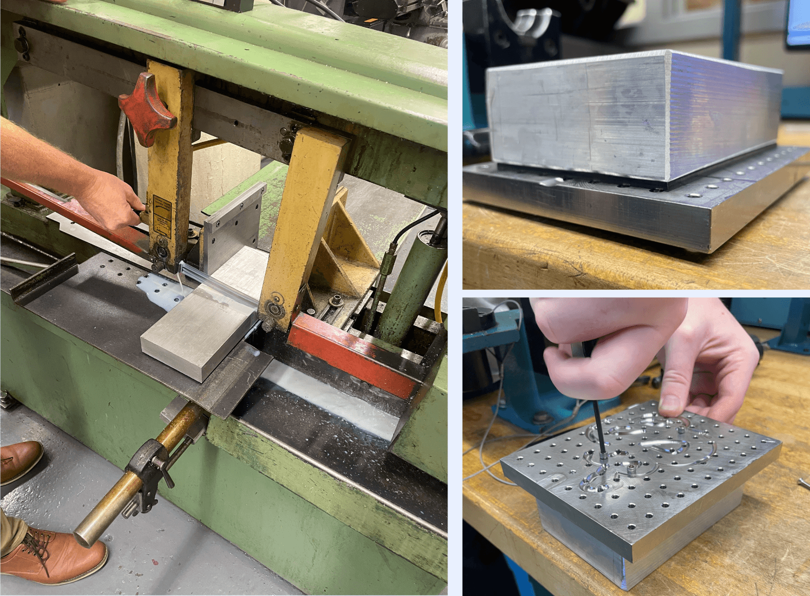
Stock setup
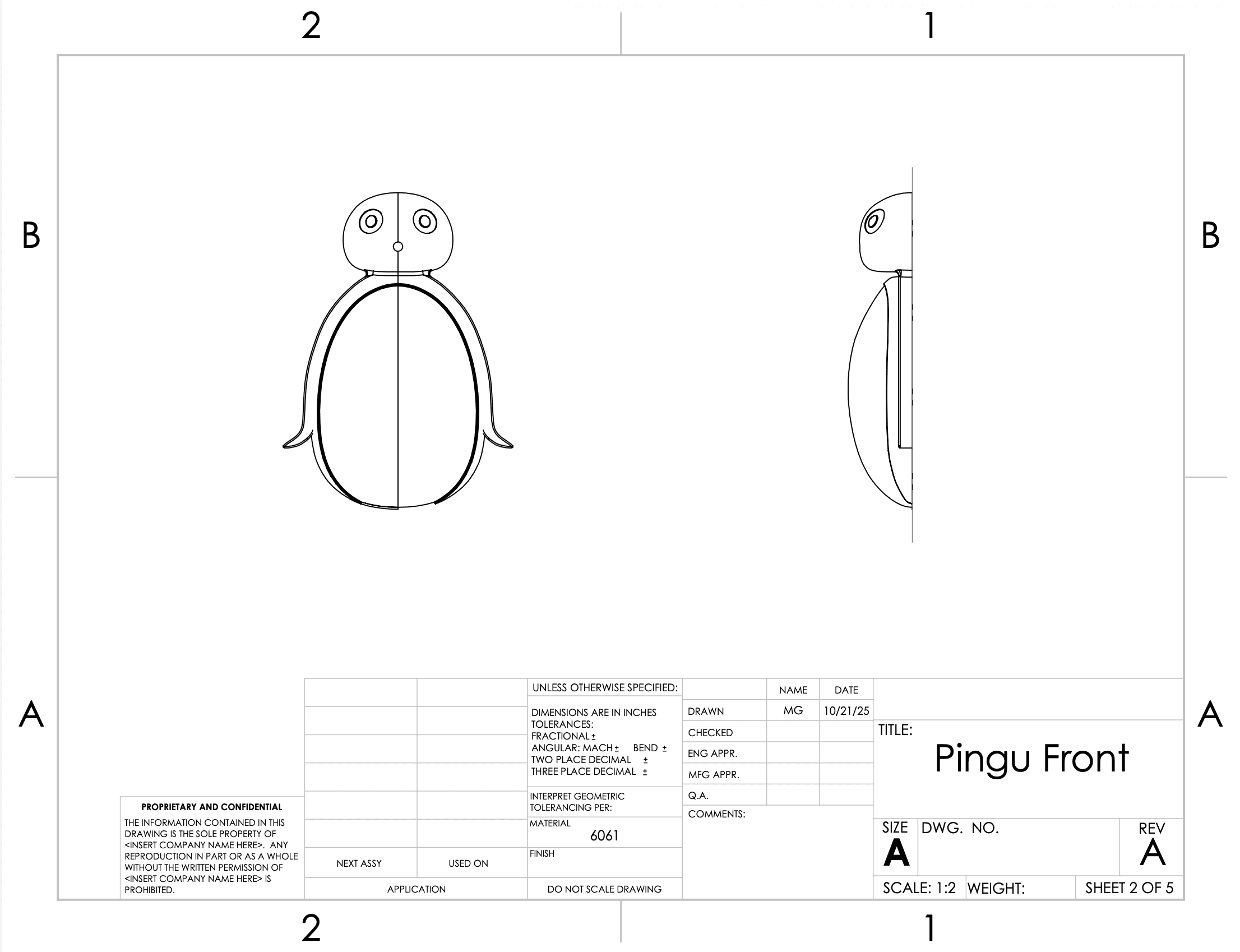
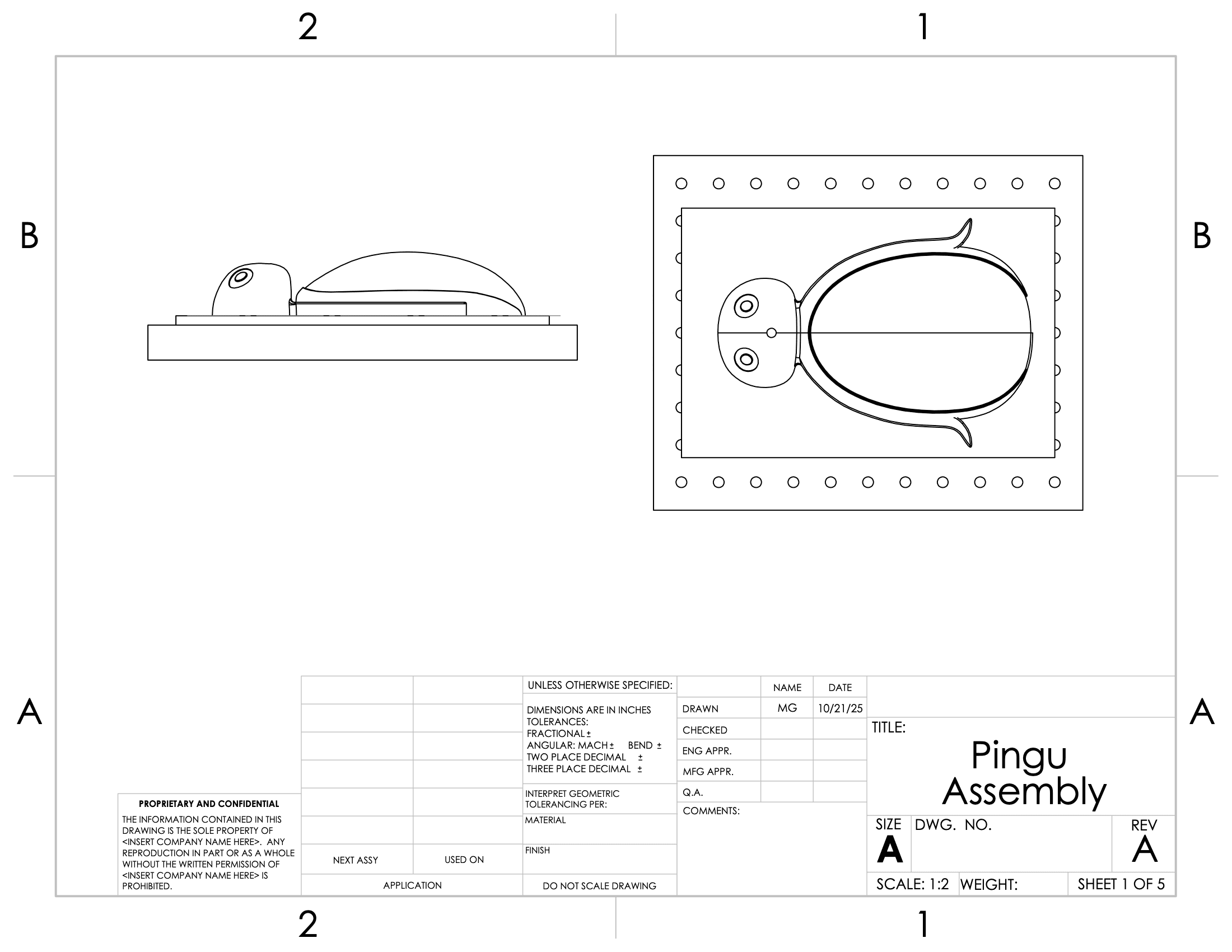
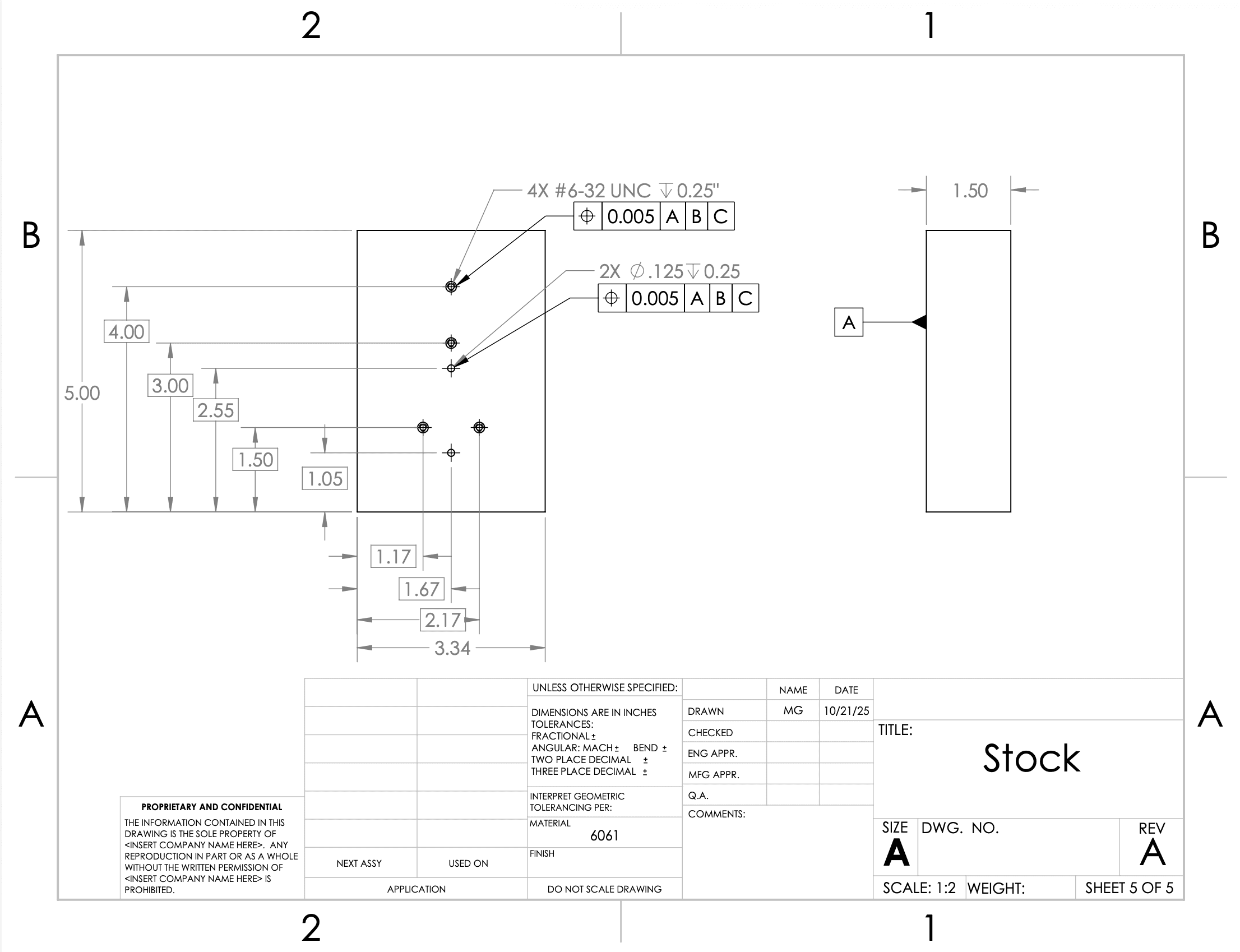
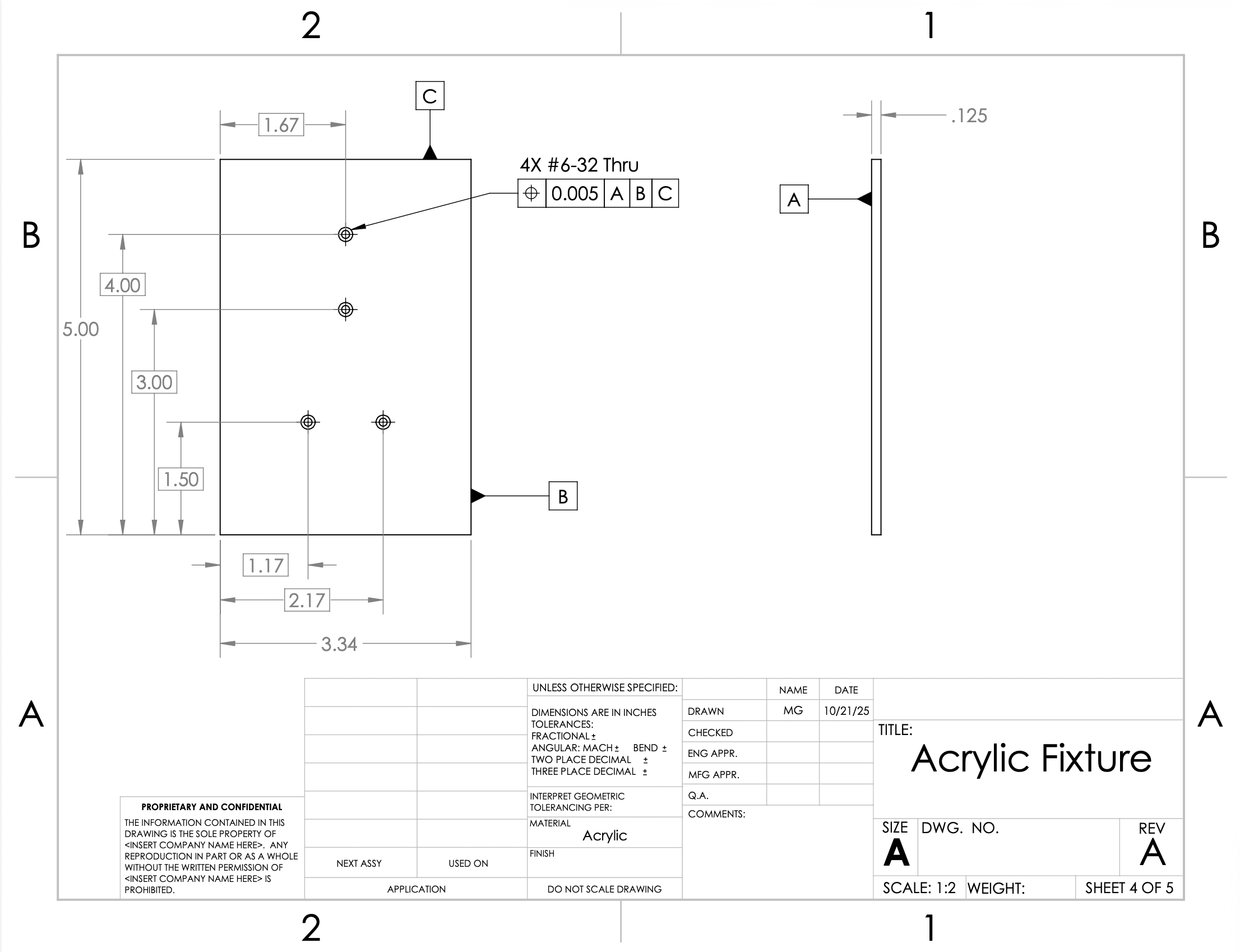
The body was split along its midplane so each half could be milled separately without a flip. The stock holes and acrylic fixture handled repeatable positioning.
MECHANICAL · CAD · MACHINING · FABRICATION
A tabletop eye-candy object machined from aluminum.
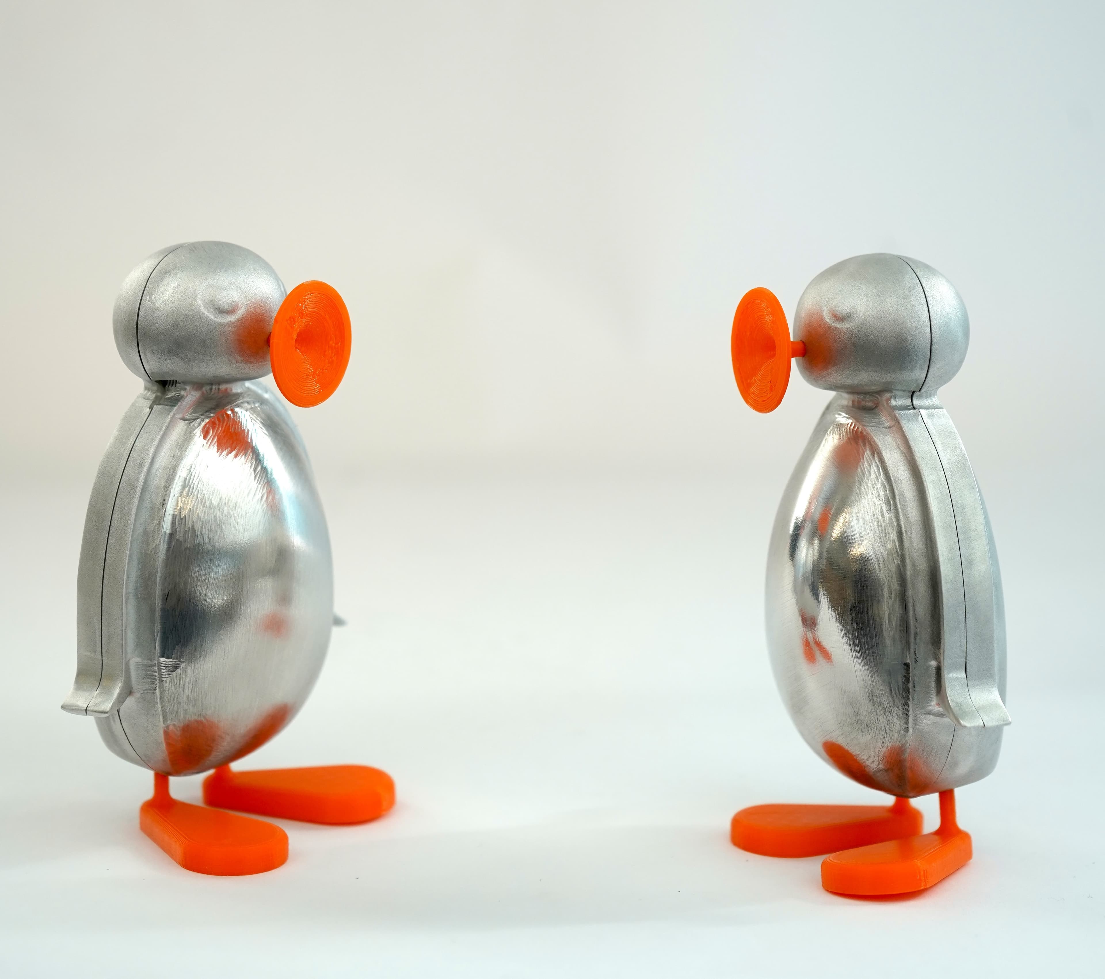
The brief was to make a small tabletop candy object from a 500 x 500 x 250 block of 6061 aluminum using the Haas Mini Mill in three weeks.
Course
IPD 5010
Team
Mark & Shreyas
Timeline
3 weeks
Process
Mini Mill · CAD/CAM · 3D print
01 · concept
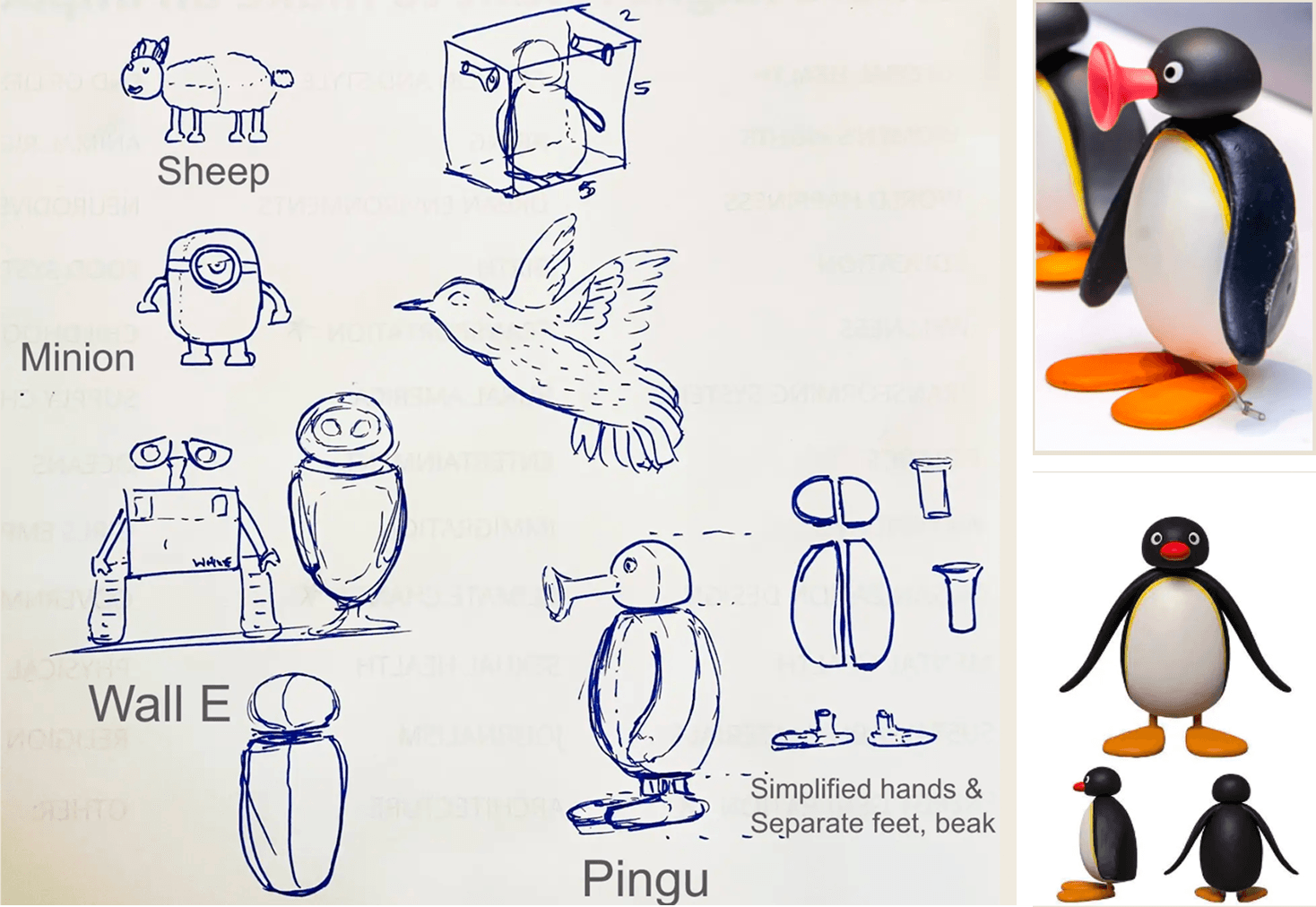
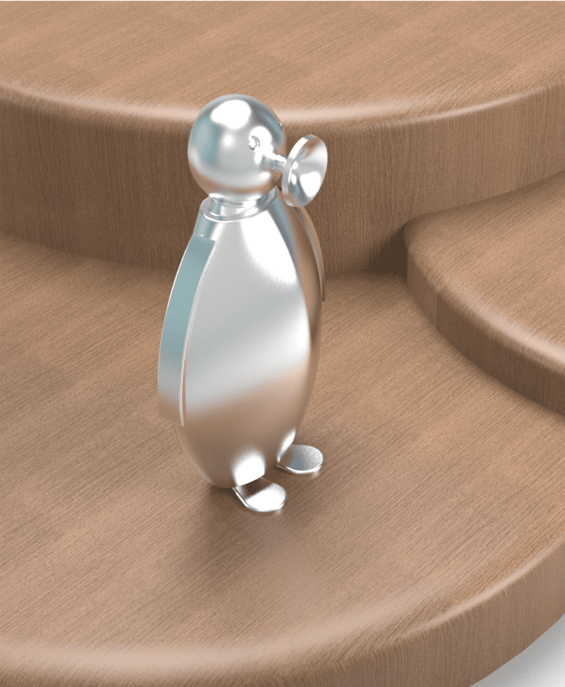
I like animated films and cartoons, so we started by sketching characters from a few favorites. After some quick ideation, Pingu felt like the right direction: playful, recognizable, and just challenging enough to make as a machined object.
02 · v1
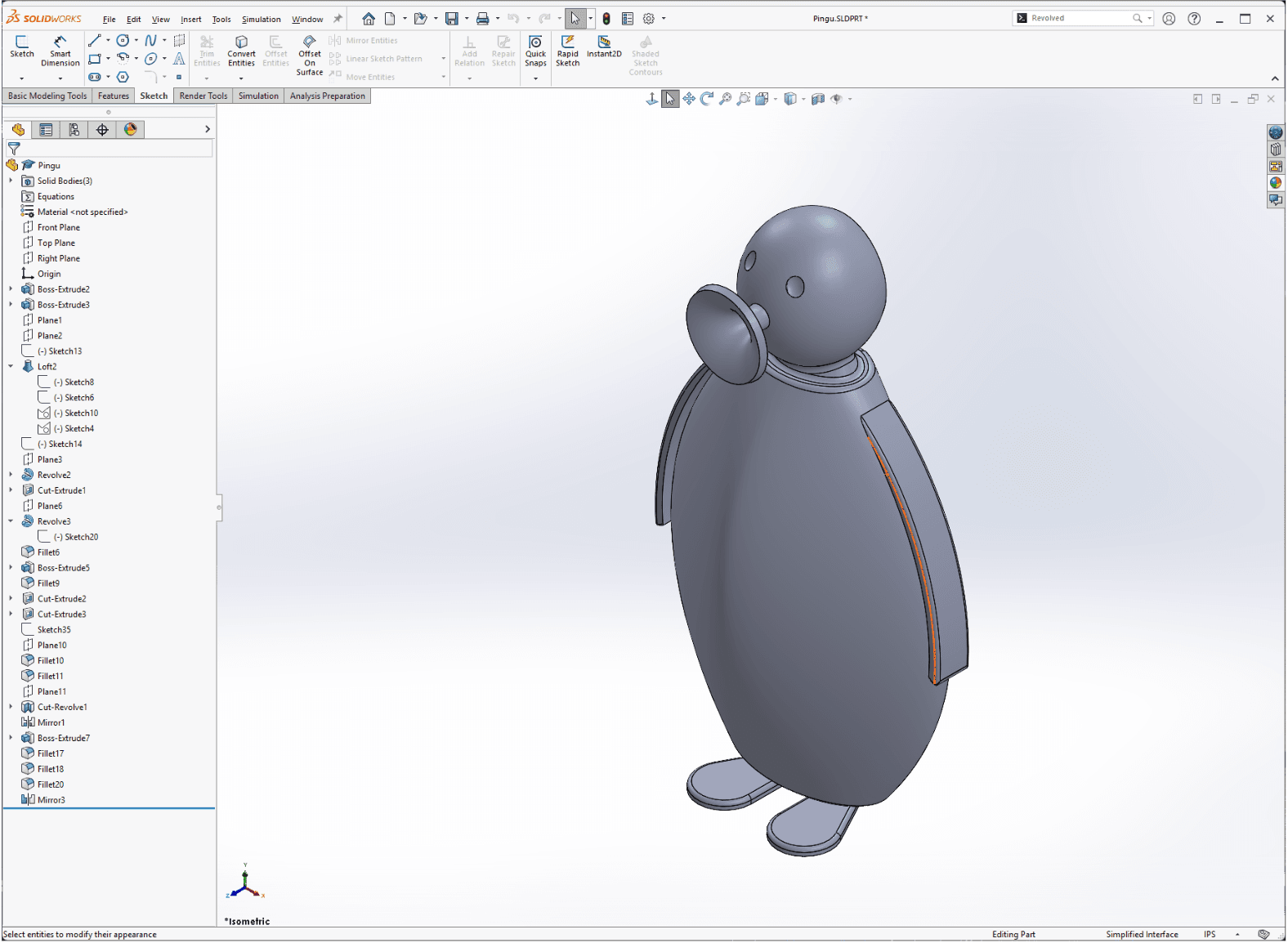
Version one assumed we could machine the full form by flipping the stock. It looked plausible on screen, but it was awkward in the Mini Mill vice, hard to mount cleanly, and the machining time was already pushing past what the project could support.
03 · v2
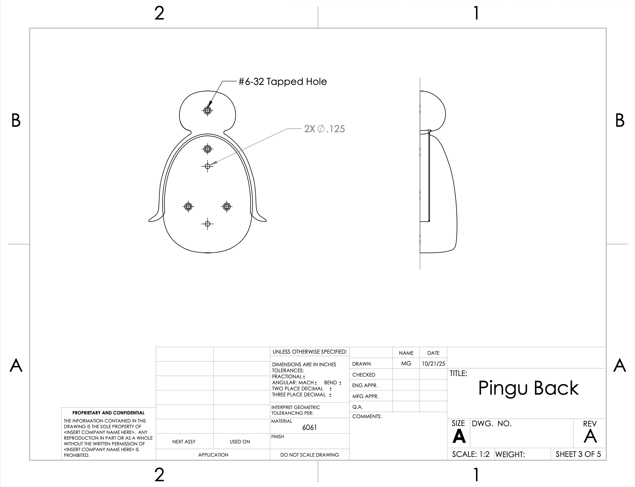
The second version became a front-and-back assembly. Each half could be milled separately with higher fidelity and less setup drama, then aligned and put together with dowel pins as one finished object.
two-part body drawings
scale prototype
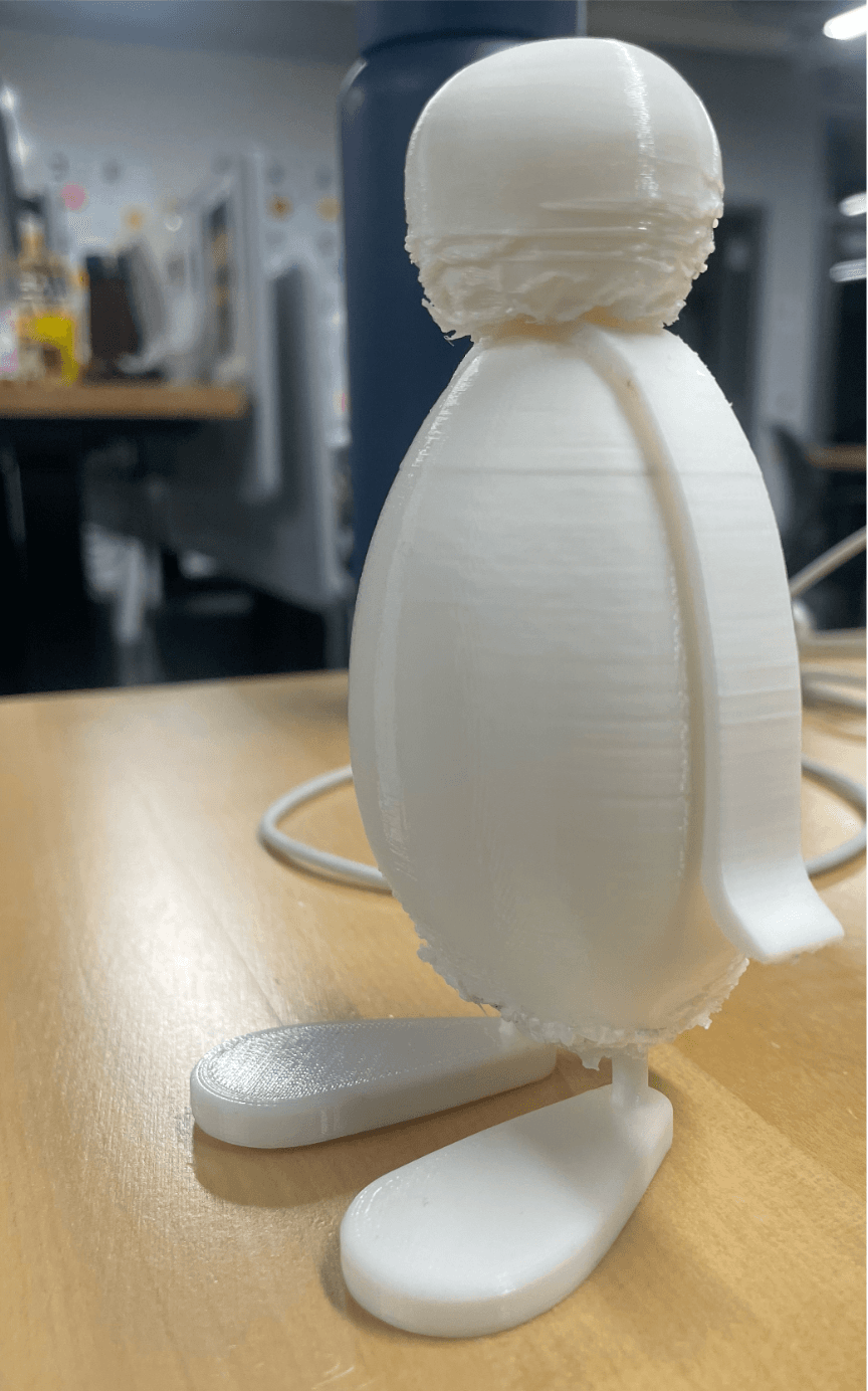
Before milling, we 3D printed a full-scale prototype to check the body proportions and stance.
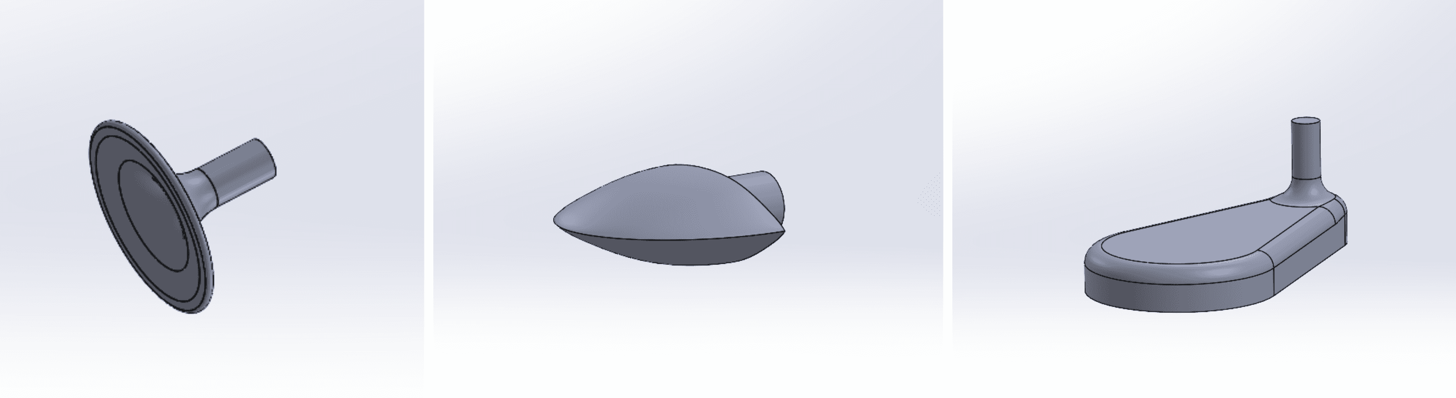
We kept the beak and feet separate from the aluminum body and planned them as PLA press-fit parts. That made the main machining simpler and we could create different beak sizes and shapes to give Pingu a bit more character.
04 · machining
Most of the work lived in the relationship between the split body, the fixture, and the Mini Mill. Each setup had to preserve the same reference logic or the two halves would never feel like one object.
01
The body was split along its midplane so each half could be milled separately without a flip. The stock holes and acrylic fixture handled repeatable positioning.
02
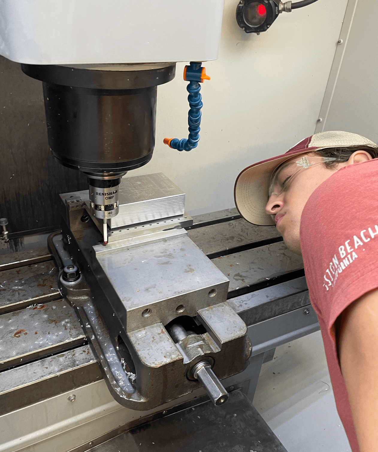
Mark checking the probe position after the stock was installed so the orientation and hole locations stayed consistent across the CAM setups.
03
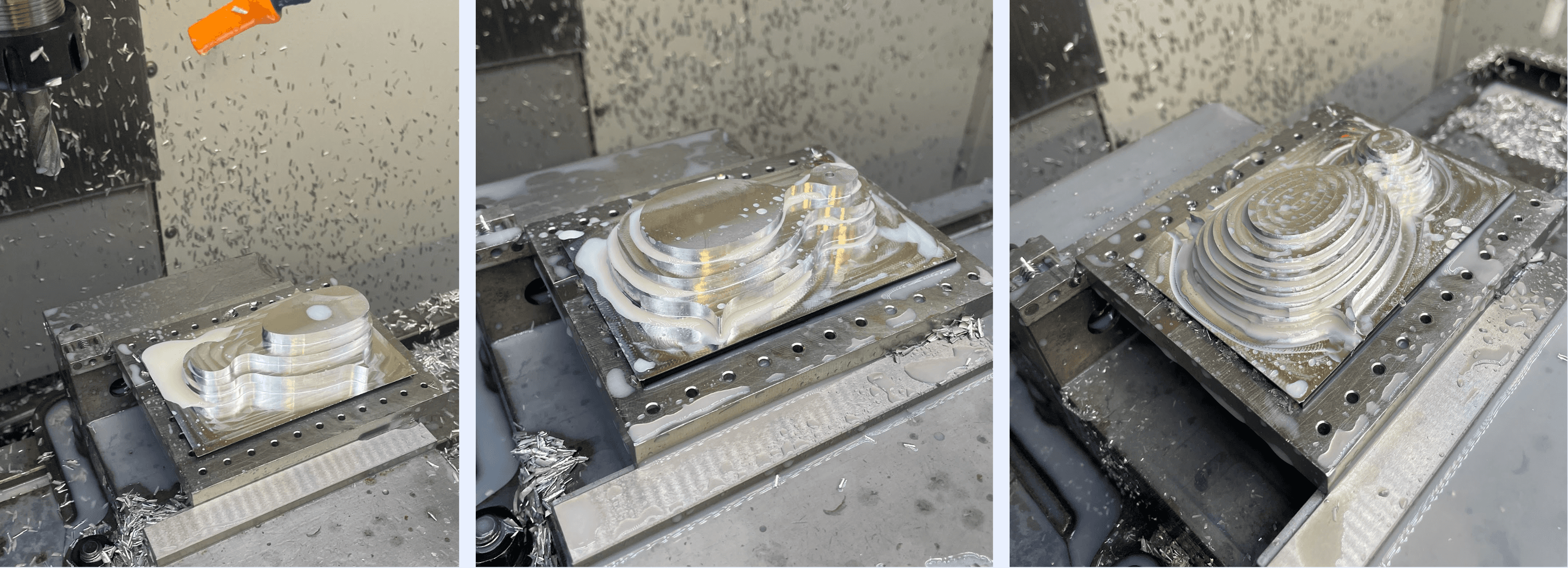
The curves were adjusted around the available tools. Switching from a 1/8 inch ball end mill to a 1/4 inch ball end mill saved time while keeping the surface close enough.
04
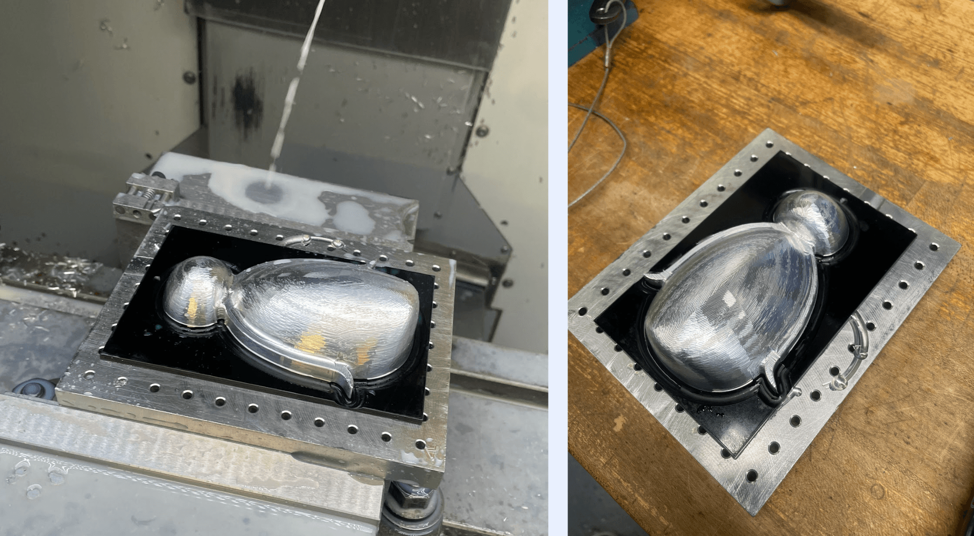
Each half needed its own CAM and careful tool numbering. The goal was getting both halves to meet cleanly.
05 · finishing
We introduced contrast with two finishing processes
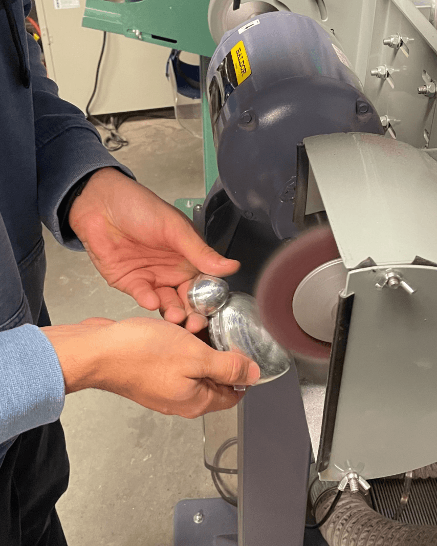
deburring and polish
The front belly was polished to keep a bright contrast against the softer blasted surfaces.
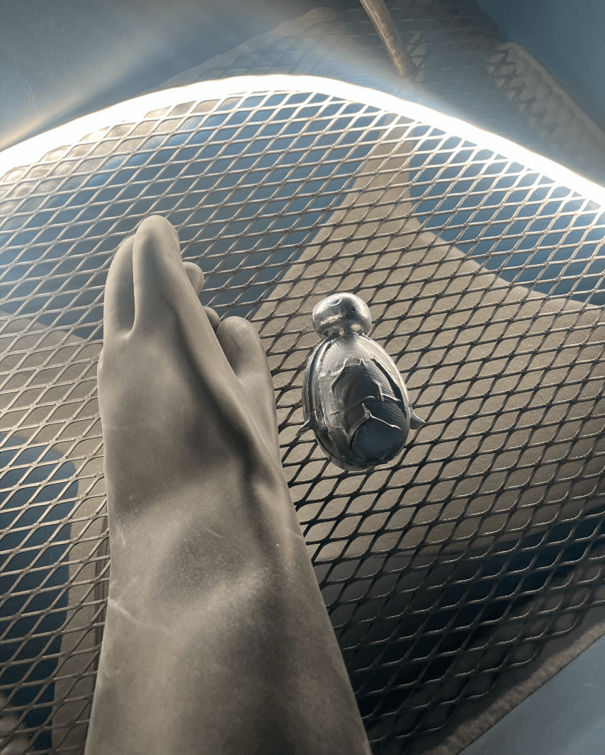
sandblasting
Masked the belly and sandblasted the body and head helping hide the tool marks and create a more uniform surface finish.
06 · learnings
07 · final